SECGlitcher (Part 1) - Reproducible Voltage Glitching on STM32 Microcontrollers

research

Voltage glitching is a technique used in hardware security testing to try to bypass or modify the normal operation of a device by injecting a glitch, or a brief but precise disruption, into its power supply voltage.

Glitching Setup

TL;DR

STM32 microcontrollers are well known as being versatile and affordable and are hence frequently being used in IoT products. In part one of our glitching blog post series, Gerhard Hechenberger and Steffen Robertz, both IoT and embedded systems security experts, will showcase their research about glitching a target device in order to skip authentication on a command line as well as to read the firmware from a controller with enabled readout protection. Further, they developed an abstraction layer for the ChipWhisperer devices with the goal to speed up the development of glitching attacks during customer projects in our hardware laboratory.

The following blog post describes our approach on voltage glitching and how we try to make it more accessible and usable during security assessments. To do this, we started tinkering with the widely used STM32 microcontroller series and built the SECGlitcher script on top of the famous ChipWhisperer tool. But first, we will briefly revisit the basics.

Voltage glitch as seen on an oscilloscope
Figure 1: Voltage glitch as seen on an oscilloscope

Introduction to Voltage Glitching

Voltage glitching is a technique used in hardware security testing to try to bypass or modify the normal operation of a device by injecting a glitch, or a brief but precise disruption, into its power supply voltage. Such attacks work by manipulating the power supply voltage of a device at a specific moment of its operation, typically when it is performing a critical operation or executing a security-sensitive function. By disrupting the power supply voltage, the targeted device may behave in unexpected ways, which is exhibited by the device as skipping instructions or executing them incorrectly. This can be exploited to achieve a range of security objectives, such as bypassing authentication, extracting secret keys, or altering the behavior of the device. The pictures (figure 1 and figure 2) below show how such an attack is set up.

Glitching setup with ChipWhisperer Pro, STM32 Nucleo development board and power supply
Figure 2: Glitching setup with ChipWhisperer Pro, STM32 Nucleo development board and power supply. The oscilloscope is located above the upper left part of the picture (not displayed).

Although many people tend to use their custom built tools, more or less professional tools are available to exploit such vulnerabilities. This includes the ChipWhisperer series, which evolved from the master thesis "A Framework for Embedded Hardware Security Analysis" by Colin O'Flynn and can be considered as the most common glitching device. We chose the same device for our work, as it is readily available.

Similar to this article by Colin O'Flynn, where he recently published some related work, we're not about to disclose a new vulnerability here. However, we're taking another step to make glitching more accessible and reproducible. A lot of work was already previously done on glitching the STM32 series, a good write-up is a blog post by Raccoon Security "Read secure firmware from STM32F1xx flash using ChipWhisperer" from 2020. However, the most widely known work exploiting this flaw on STM32 devices is probably the recovery of $2 million in crypto coins by Joe Grand from 2022, which is built up on the work of Kraken Security Labs from 2020 (read it here: "Kraken Identifies Critical Flaw in Trezor Hardware Wallets").

Attacking the STM32 Series

The STM32 series are 32-bit microcontrollers based on the Arm Cortex-M processor and are widely used in embedded systems. Different variants are suitable for low-power as well as for high-performance operations. One of its security options is the so-called Readout Protection (RDP) . The STM32 offers three different levels:

RDP Level 0: No protection

  • Full debugging is allowed
  • Full access while in system bootloader

RDP Level 1: Read protection

  • Access (read, erase, program) to Flash memory is forbidden while debugging
  • Other memories such as the bootloader memory can be accessed via JTAG
  • Access (read, erase, program) to any memory is forbidden while in system bootloader
  • Everything else can be read, e.g. RAM and registers
  • Reset to RDP level 0 erases whole Flash memory

RDP Level 2: Read & debug protection

  • Debugging is forbidden by disabling the JTAG and SWD interfaces
  • Starting system bootloader is forbidden
  • Reset to RDP Level 0/1 is not possible

To read the Flash memory on RDP2 locked devices, two protection levels must be circumvented.

RDP2 Downgrade to RDP1

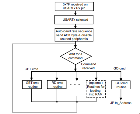
On boot, the RDP register value is checked. A specific value has to be set for RDP2 (0xCC) and RDP0 (0xAA), all other values default to RDP1 (however, often 0xBB or 0x55 is set). Therefore, if the read operation on the RDP register reads a wrong value (due to a voltage glitch), the device will think it's in RDP level 1. Thus, debug interfaces and the bootloader will become accessible.
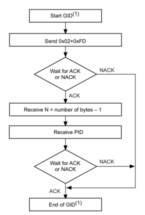
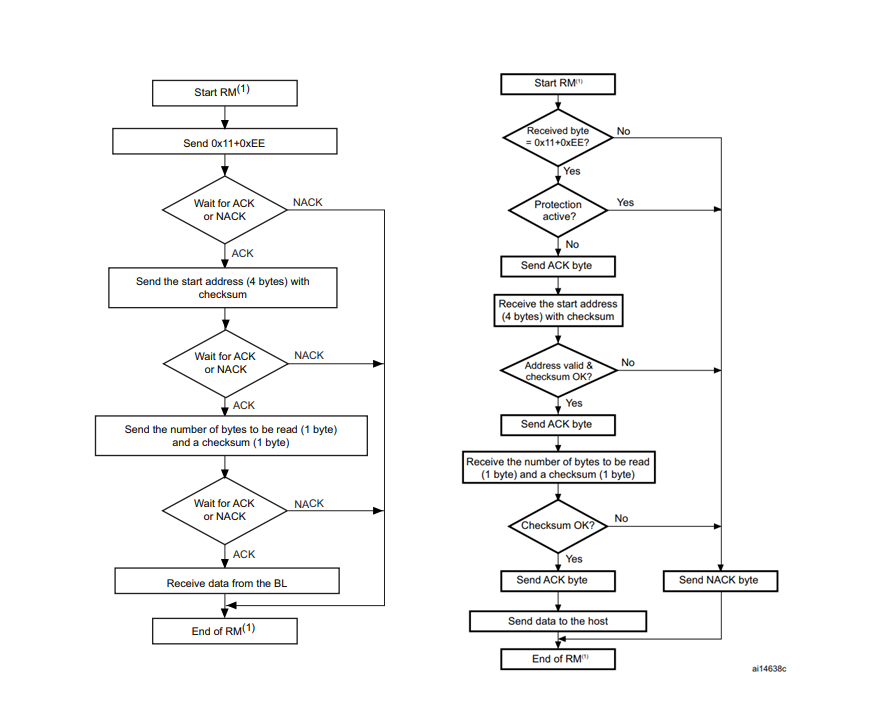
RDP1 Memory Reading

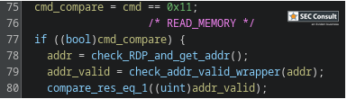
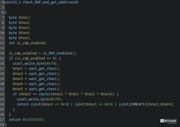
The internal system bootloader is available with RDP level 1 and provides a "Read Memory" operation which reads 256 bytes from a user-supplied memory address. However, this operation is not allowed in RDP1. This is ensured by the microcontroller checking the RDP state before every read operation. If this check is tampered with (by a voltage glitch), it will be skipped and 256 bytes of memory read. By glitching the read command repeatedly, 256 byte firmware chunks can be read and reassembled into a complete firmware dump. 

SECGlitcher

During the last years, much work was done on Voltage Glitching attacks, as already described in the introduction above. However, we noticed that recreating glitches can be hard, mostly due to the usage of custom hardware and often unpublished glitching parameters and setups. Therefore, we took a structured approach which can hopefully be extended in the future on other chips and boards:

We created the SECGlitcher, which is based on the well-established ChipWhisperer API, but is easier to use for default use cases such as UART or GPIO triggers.

Features

We developed the SECGlitcher as we noted, that glitching scripts across all boards are always structured similar. So why not create a simple class that wraps all of the init commands and also gathers the results? This results in smaller, clearly structured scripts that can be easily compared across different boards and chips. 

Reproduce glitches with parameters: During our glitching experiments, we were always struggling with the same question: What do we use as initial search parameters? Depending on how closely we guess the glitch duration as well as trigger offset, we can find valid glitches after minutes. However, if our estimate is way off, we will take days to discover interesting glitching ranges. Thus, we decided to include a database in the SECGlitcher, which contains valid glitch width settings that we have discovered previously for each MCU. Hence, your valid parameters shouldn't be off too far (of course this also depends on the used board and capacitance of the power rail). 

Easy headless usage: The use of Jupyter notebooks as featured by the ChipWhisperer may be great for some initial experiments, however, for conducting glitching tests in an efficient and scalable manner, we needed a solution that can be conveniently controlled remotely, e.g., is able to run on a (headless) server. Therefore, the SECGlitcher class is built to be used in command-line only scripts (though we implemented some interactive elements, just in case you want to showcase some stuff).

Convenient data aggregation: The need for fault-proof and convenient data aggregation comes right after the previous feature. To prevent data loss, data can not only be printed out to the console but can also be saved as CSV file. These CSV files, created from one or multiple glitching attempts, can subsequently be aggregated and visualized by a provided helper script. With this, it is possible to show potential valid glitching parameters of multiple (partial) tries.

Easy setup: An easy setup is important to keep the entry barrier low, luckily, using the SECGlitcher class is simple: Create a new virtual environment and install the chipwhisperer as well as some other required packages with PIP. That's it.

Modified Nucleo STM32L073RZ development board
Figure 3: Modified Nucleo STM32L073RZ development board
Marked capacitors in the schematic need to be removed (Source: MB1136 sheet 1)
Figure 4: Marked capacitors in the schematic need to be removed (Source: MB1136 sheet 1)
Marked capacitors in the schematic need to be removed (Source: MB1136 sheet 2)
Figure 5: Marked capacitors in the schematic need to be removed (Source: MB1136 sheet 2)

Setup

For glitching, the Crowbar Glitching approach was chosen, where the power rail of the chip is shorted to ground. The basic setup for glitching Nucleo boards is described exemplary for the STM23L073RZ board. To start, the board needs some modifications. This includes removing most of the decoupling capacitors on the power line and adding a pin header where the glitcher can short the power rail. The modified board and the schematics (available as MB1136) for the removal of the capacitors are shown below in figure 3, 4 and 5.

Chip supply voltage curve while being glitched
Figure 6: Chip supply voltage curve while being glitched

The pin header was added to the now empty pads of the C28 capacitor. C23 was added again to limit the voltage overshooting after the glitch.

Why do we have to remove most of the capacitors? Capacitors "store" power, if a power rail with a huge capacitance is shorted, the voltage will drop to zero only slowly. If there is only a small capacity, the voltage drop will be steep - and this is what we want for glitching. However, if there is some kind of power management, the board will try to keep the voltage stable and thus causes an sharp overshoot as soon as the short is released (compare to trying to push a closed door open when suddenly someone opens it from the other side). This might damage the chip, therefore, we typically keep some capacitors.

This setup will now result in a glitch which looks like on the oscilloscope as shown below in figure 6. There are four different parts of the chip voltage curve:

  • A: Normal operation, constant 3.3V
  • B: Glitch, power rail is shorted to ground while the voltage regulator tries to keep the voltage up but fails in doing this
  • C: The short is released, the power spikes due to the voltage regulator still trying to push the voltage back (up)
  • D: The voltage regulator starts to recover the constant 3.3V and stabilizes the voltage rail after some transient oscillation

Setting up the Glitch

When glitching a different board, there are multiple things to consider in the ChipWhisperer configuration. The ChipWhisperer always has to be clocked, as we do not have access to the target internal clock, we just select a high frequency that the ChipWhisperer can generate on its own. However, we will not be synchronized to the target's clock. Hence, we cannot control if we glitch at the beginning of the target's instruction execution or at the end of it.

The next important metric is the glitch width. This is the time for which the power rail is shorted to ground. It will be measured in clock cycles of the ChipWhisperer. This is one of the most important glitch characteristics. If its chosen too small, the voltage will not drop far enough and the chip's operation is not affected. If it's chosen too high, the chip will be reset and restart its operation from the first instruction. A proper glitch, were the MCU is not reset, but also does not operate properly is right in the middle of these two values. The second parameter is the glitch offset. This parameter will wait for a trigger (e.g. a pin state changing or a certain byte being received over UART) and then wait for a set amount of ChipWhisperer clock cycles before inserting the glitch. Thus, this parameter can be used to time the glitch with the instruction or register load that we want to affect. 

As you can tell, it is a very tedious task to identify these parameters for a blackbox board and chip. This is why we created the SECGlitcher. The script comes with a YAML configuration file where we store all valid glitching widths that we discovered for a certain board. This way, we can reuse old settings and improve the search range for valid parameters. We included the offset for some demo applications. However, this parameter cannot be estimated beforehand, as it changes for each program (unless you have access to the compiled code, then of course you could count instruction cycles from the trigger and estimate how many ChipWhisperer cycles would equal this case). In order to give us the most precision in our scanning, we run the ChipWhisperer's clock at 100MHz.

The SECGlitcher is setup as a abstract class that you have to overload. Some function are already implemented, while others have to be written from scratch. We will now show an example for a simple password check glitch on the Nucleo STM23L073RZ board. The target is running following example code:

Target MCU code

HAL_Init();
SystemClock_Config();
MX_GPIO_Init();
MX_USART2_UART_Init();
 
char set_pw[] = "mysupersecurepassword";
char check_pw[128];
int check_ok = false;
 
char s1[] = "Init successful\n";
HAL_UART_Transmit(&huart2, (uint8_t*)s1, sizeof(s1), HAL_MAX_DELAY);
 
while (!check_ok) {
  char s2[] = "Please enter password:\n";
  HAL_UART_Transmit(&huart2, (uint8_t*)s2, sizeof(s2), HAL_MAX_DELAY);
   
  int i = 0;
  volatile char c = '\0';
  while (c != '\n' && c != '\r' && i < 127) {
    HAL_UART_Receive(&huart2, (uint8_t*)&c, 1, HAL_MAX_DELAY);
    HAL_UART_Transmit(&huart2, (uint8_t*)&c, 1, HAL_MAX_DELAY);
    if (c == '\n' || c == '\r') {
      check_pw[i] = '\0';
    } else {
      check_pw[i] = c;
    }
    i++;
  }
  check_pw[127] = '\0';
 
  if (strcmp(set_pw, check_pw) == 0) {
    check_ok = true;
  }
}
  
HAL_GPIO_TogglePin(LD2_GPIO_Port, LD2_Pin);
 
char s3[] = "Welcome!\n";
HAL_UART_Transmit(&huart2, (uint8_t*)s3, sizeof(s3), HAL_MAX_DELAY);
char s4[] = "This is your secret: supersecretstring\n";
HAL_UART_Transmit(&huart2, (uint8_t*)s4, sizeof(s4), HAL_MAX_DELAY);

As we have previously searched for valid glitching parameters on this board, they are already included in the configuration file.

stm32l073:
  pw: [27, 29, 150, 159]

Subsequently, a glitching script can be created using the SECGlitcher as follows:

class MyGlitcher(SECGlitcher):
    def __init__(self, reset_pin='nrst', interactive=False):
        super().__init__(reset_pin)
        self.interactive = interactive
        self.uart = None
 
    def dut_check_init(self):
        log = self.uart.read_until("password:")
        if log.endswith(b"password:\n\x00"):
            return True
        else:
            print("Boot failed!")
            self.scope.io.nrst = "low"
            time.sleep(1)
            return False
 
    def check_glitch(self):
        check = self.uart.readline()
        if b"elcome" in check or b"secret" in check:
            self.add_success()
            print("Glitch successful: Width: {}, Offset: {}".format(*self.success_params[-1]))
            if self.interactive:
                print("Press ENTER to continue")
                input()
        else:
            pass
 
    def dut_uart_init_before_reset(self):
        self.uart = serial.Serial('/dev/ttyACM0', 115200, timeout=0.1)
 
    def dut_uart_write(self):
        self.uart.write(b"\r\n")
 
 
glitcher = MyGlitcher(interactive=True)
glitcher.trigger_setup(trigger='uart', uart_pattern=['\r'])
glitcher.print_config()
glitcher.run(target="stm32l073", app="pw")
glitcher.exit()
glitcher.print_results()
glitcher.save_results()
glitcher.plot_results()
Password check glitching in action

The short GIF below shows the password check glitching in action. After several tries, the glitch turns out just right and skips the password check without entering the correct password, giving back the secret (Figure 7: Password check glitching in action).

RDP1 Memory Reading

After downgrading the RDP level to 1, we can glitch the memory read command in the now accessible bootloader. STM describes how to enable the bootloader in AN2606. We plan on using the UART bootloader on an STM32F429ZI Nucleo board. According to the application note, this means that we can use USART3 or USART1  with 115200 8E1 configuration. Further, the "Boot0" pin needs to be pulled high in order to activate the bootloader. Luckily, this pin as well as PB10/11 for USART3 are exposed on the Nucleo header. AN3155 now describes the actual used protocol. For clarity, we will omit the needed checksum in the following description. An extensive description of the internal bootloader process can be found in the appendix.

To activate the bootloader, the activation command (0x7F) must be sent. After that, we can use the GET_ID command (0x02) to check for proper activation, which should return an ACK (0x79) and the PID (here 0x429). Knowing that we properly activated the bootloader, we can now execute the interesting READ_MEMORY command (0x11) which must be followed by four address bytes (e.g., 0x80000000) and the number of bytes to be read (0xFF), each one acknowledged by receiving ACK (0x79).

Using our SECGlitcher, the dumping script is fairly easy. We evaluated, that the bootloader glitches with a glitch width between 23 and 24. The offset of our trigger byte (the UART transmission of 0x11) equals 9050 to 9150 cycles. This is now implemented as "bl_mem" configuration of our glitcher.

glitch_bootloader_to_download.py

from SECGlitcher import SECGlitcher
import time
import signal
import hexdump
from spd3303x import SPD3303X
from stm32bootloader import STM32SerialBootloader
 
 
def power_cycle():
    with SPD3303X.ethernet_device("x.x.x.x") as dev:
        dev.CH1.set_output(False)
        time.sleep(0.1)
        dev.CH1.set_output(True)
        time.sleep(0.5)
 
 
def int_handler(signum, frame):
    global glitcher
    glitcher.exit()
    glitcher.print_results()
    glitcher.save_results()
 
 
signal.signal(signal.SIGINT, int_handler)
 
 
class MyGlitcher(SECGlitcher):
    def __init__(self, dump_addr, dump_len, dump_filename, reset_pin='nrst'):
        super().__init__(reset_pin)
        self.current_dump_addr = dump_addr
        self.current_dump_len = dump_len
        self.dump_filename = dump_filename
        self.uart = None
 
    def dut_uart_init_before_reset(self):
        time.sleep(0.1)
 
    def dut_uart_init_after_reset(self):
        time.sleep(0.1)
        try:
            self.uart = STM32SerialBootloader("/dev/ttyACM1", baud=115200)
            self.uart.cmd_get_id()
        except ValueError:
            print("Bootloader not Activated properly! Something is wrong!")
            self.scope.io.nrst = "low"
            power_cycle()
            time.sleep(0.1)
            return False
        print("Bootloader available")
        return True
 
    def dut_uart_write(self):
        self.uart.cmd_read_memory_part1()
        print("Using width: {} Offset: {} Success: {}".format(self.current_width, self.current_offset, len(self.success_params)))
 
    def check_glitch(self):
        state = self.uart.cmd_read_memory_part2()
        if state == 0:
            try:
                len_to_dump = 256 if (self.current_dump_len // 256) else self.current_dump_len % 256
                data = self.uart.cmd_read_memory_part3(self.current_dump_addr, len_to_dump)
                #print(data)
                if len(data) == len_to_dump:
                    if data != b"\x79" * len_to_dump:
                        with open(self.dump_filename, 'ab+') as f:
                            f.write(data)
                        self.current_dump_addr += len_to_dump
                        self.current_dump_len -= len_to_dump
                        print("Dumped using width: {} offset: {} success: {}".format(self.current_width,
                                                                                     self.current_offset,
                                                                                     len(self.success_params)))
                        print("Dumped 0x{:x} bytes from addr 0x{:x}, {:x} bytes left".format(len_to_dump,
                                                                                             self.current_dump_addr,
                                                                                             self.current_dump_len))
                else:
                    print("Missing some data, but got")
                    hexdump.hexdump(data)
                self.add_success()
            except Exception as e:
                print(e)
                print("Nothing read")
 
 
glitcher = MyGlitcher(0x0800_0000, 0x200000, dump_filename="dumped_firmware.bin")
glitcher.trigger_setup(trigger='uart', parity='even', uart_pattern=[0x11])
glitcher.print_config()
 
power_cycle()
while glitcher.current_dump_len > 0:
    glitcher.run(target="stm32f429", app="bl_mem")
 
glitcher.exit()
glitcher.print_results()
glitcher.save_results()
glitcher.plot_results()


Glitched MEMORY_READ command on STM32F429ZI
Figure 8: Glitched MEMORY_READ command on STM32F429ZI

A working glitch is shown in the next figure 8. Notice the end of the decoded UART transmission of 0xEE (checksum of 0x11) as channel S1 at the bottom.

Recovered sample program firmware from STM32F429ZI
Figure 9: Recovered sample program firmware from STM32F429ZI

Running the script over night resulted in 622 successful glitches and thus roughly 155kB of protected firmware. Examining the "dumped_firmware.bin file results in the disclosure of the secret password "MySecretPasswordString", as shown in figure 9:

Conclusion

At the beginning of this project, we decided it would be fun to glitch some STM32 microcontrollers, as we would encounter them frequently in all sorts of IoT devices. We would have never imagined how far down the rabbit hole we would have to go. 

During our initial research of papers about STM32 glitching, we found some other companies that pulled it off before. However, nobody was posting their parameters or details about the how. That's why we decided to create the SECGlitcher class. It's supposed to store rough timing areas for boards and MCUs, so that only a small space has to be searched. Further, it handles initialization and some generic trigger setups to keep the code base small and tidy.  Using our class, we were able to showcase some successful glitches, including the skipping of a password check via a UART command line and reading memory via the bootloader of an locked STM32. 

However, we also ran into some unexpected obstacles, that no one else mentioned in their blogposts or papers yet. We are unsure, if this behavior is solely due to the choice of STM32 model. While this behavior slows down the process of extracting the whole flash of an STM32, it does not change the underlying vulnerability. We are still able to read all contents from a locked device. 

With our experiments we were able to show that the STM32 series of microcontrollers must be seen as insecure, even if readout protection measures are active. An attacker is able to skip instructions and thus bypass checks, which can be turned into a leak of the full firmware. The SECGlitcher class significantly improved the usability of glitching attacks in our day to day projects, as it is faster and simpler to setup and improves results.

Stay tuned for part two of our glitching series, where we will glitch a STM32 from RDP2 to RDP1 and then dump its contents. 

Appendix: Setting Even Parity for UART on ChipWhisperer (Tech Deep Dive)

The STM32 bootloader uses UART communication with an even parity bit, as described in the AN3155 Application Note. This turned out to be a major challenge for using the ChipWhisperer for this work, as the ChipWhisperer does not officially support any parity bit for its UART interface. This was also recently mentioned in a article by the creator of the ChipWhisperer, Colin O'Flynn itself, where he noted that "custom bitstream for the ChipWhisperer-Pro is needed due to the even parity requirement of the bootloader". Our work started before this article was published, and back then we found a different solution to this problem. It is true that the ChipWhisperer does not officially support parity bits, however, at least even parity is supported in the FPGA implementation since April 2021. So there was no need for a custom bitstream for us. We only had to find out how to use it.

The corresponding Github issue from April 2021 shows that some UART configuration registers were exposed to the interface to be used by Python. The UART implementation "targ_async_receiver" is instantiated in the "reg_decodeiotrigger" line 198, where the IO registers are parsed. Here, byte 2 of "reg_trig_cfg" is set as "module_specific", and the "even_parity" bit turned out to be the first bit of this byte. Therefore, we are happy to present you the solution to set the even parity bit mode on the ChipWhisperer UART below, where the even parity bit gets set.

CODE_READ = 0x80
CODE_WRITE = 0xC0
ADDR_DECODECFG = 57
ADDR_DECODEDATA = 58
data = self.scope.decode_IO.oa.sendMessage(CODE_READ, ADDR_DECODECFG, Validate=False, maxResp=8)
data[1] = data[1] | 0x01
self.scope.decode_IO.oa.sendMessage(CODE_WRITE, ADDR_DECODECFG, data)

This code is also implemented in the SECGlitcher class.

STM32 bootloader with quick answer
Figure 10: STM32 bootloader with quick answer
STM32 bootloader with delayed answer
Figure 11: STM32 bootloader with delayed answer

Appendix: The Story of the Inconsistent Timing (Tech Deep Dive)

While trying to execute the glitch for reading the memory, we made a seemingly odd observation: Sometimes, the value in the RDP register (which controls the lock state) changed to 0x55 and sometimes also the SPRMOD register (a special feature for write protection in this STM32 model) changed to 0x01 - but why? We never write to the register in our executed path. We came to the conclusion that most likely we are glitching on a different bootloader path. Further inspection assured us in this guess, as we made another odd observation: The UART response was not constant but shifting around randomly in a pretty big timeframe window. This is shown in the next two figures (10 & 11), where a difference in up to 8us can be observed (S1 shows the decoded UART communication). As we glitch on a fixed offset from the command, it seems that in reality, we are glitching in an extremely in-deterministic way.

USART implementation block diagram (Source: RM0090 Figure 296)
Figure 12: USART implementation block diagram (Source: RM0090 Figure 296)

After ruling out several other seemingly possible causes, we examined the different clock domains of the UART hardware and the chip itself. The UART supports a maximum baud rate of 115200, which is still slow compared to the 60MHz that the core is running at during bootloader execution. An overview of the implemented UART hardware is given below in figure 12.

Scatter plot and distribution of UART response timing for baudrate 9600
Figure 13+14: Scatter plot and distribution of UART response timing for baudrate 9600
Scatter plot and distribution of UART response timing for baudrate 115200
Figure 15+16: Scatter plot and distribution of UART response timing for baudrate 115200

From the bottom of figure 12, we see that the core clock fPCLKx is modified by a USARTDIV divider (based on the baudrate) and an additional sampling divider before it is used as transmitter and receiver clock. This means the hardware will run significantly slower than the internal core. All data that is sent and received via UART must cross from the slow to the fast clock domain (or vice versa). To validate our observation, we decided to do a simple statistical analysis on the answer delay using different baudrates. If the average delay correlates with the baudrate, the delay is caused by the slow UART clock domain.

Multiple plots were created for 1000 executions, the ones for the fastest and slowest baudrate checked are shown below in figure 13 and 14:

STM32 bootloader activation sequence (Source: AN3155 Figure 1)
Figure 17: STM32 bootloader activation sequence (Source: AN3155 Figure 1)

The plots show a huge change in delay for the different baudrates (with a ratio of 12:1).

Statistics for baudrate 9600

  • Min. delay: 59.012us
  • Max. delay: 163.130us
  • Avg. delay: 104.118us

Statistics for baudrate 115200

  • Min. delay: 4.400us
  • Max. delay: 15.628us
  • Avg. delay: 11.228us

When we take a look at the average delay, it has a ratio of roughly 9.3:1. If we assume a fixed base-delay (due to processing and calculating the answer), this aligns quite well with our assumption. It seems that the delay due to the slow clocking of the UART hardware is an inherent obstacle here for efficient glitching and may lead to unintended side effects due to shifted execution parameters. However, the effects may be mitigated by using only the shortest feasible glitch delay parameters (as the functions responsible for some unintended side effects are located after the MEMORY_READ command).

Appendix: The STM32 Bootloader

Her we will summarize the important parts of the bootloader protocol documented in AN3155. The following flowchart (figure 17) shows the activation sequence of the bootloader:

GET_ID command sequence (Source: AN3155 Figure 6)
Figure 18: GET_ID command sequence (Source: AN3155 Figure 6)

Therefore, initially, we have to transmit 0x7F to activate the UART bootloader loop. The GET_ID command to check the proper activation is implemented as follows (figure 18):

READ_MEMORY command sequence for host (Source figure 19: AN3155 Figure 8) and device (Source figure 20: AN3155 Figure 9)
Figure 19+20: READ_MEMORY command sequence for host (Source figure 19: AN3155 Figure 8) and device (Source figure 20: AN3155 Figure 9)

We can send 0x02 and 0xFD (as checksum), and if the bootloader is fully operational, an ACK (0x79) and the PID (here 0x429) will be returned. After that, the READ_MEMORY command can be used and reviewed below.

STM32 bootloader implementation for reading UART commands
Figure 21: STM32 bootloader implementation for reading UART commands
STM32 bootloader implementation for branching to the READ_MEMORY command
Figure 22: STM32 bootloader implementation for branching to the READ_MEMORY command

Figure 19 shows a fairly simple command. The user selects the command by sending 0x11 and its checksum (0xEE). Once an ACK is received, the user can send an address (e.g. 0x8000000 for start of FLASH memory) and again the checksum (which is created by XOR-ing all address bytes). Once the MCU accepts the address, an ACK is issued. Now the amount of bytes to read can be sent. Usually this will be 0xFF and its checksum 0x00 to dump 256 bytes and thus the largest amount possible. However, we are in RDP1 and therefore the command will never be ACKed. This can be seen in the flowchart that the device evaluates (figure 20).

The only way to dump memory seems to be to glitch the "Protection active?" check. But how is this check implemented exactly? We decided to dump the bootloader code (starting at 0x1fffc000) and analyze it in Ghidra.

First, an infinite loop resets the watchdog and then receives two bytes from the UART. These two bytes are the command and its checksum. Then, the checksum is verified. If the checksum is correct, we drop into a large if-else statement. As we are interested in the READ_MEMORY command, we search for the statement that compares the cmd variable to 0x11. This can be found on line 75 of the analyzed code in figure 22:

STM32 bootloader implementation to check RDP and read memory at given address
Figure 23: STM32 bootloader implementation to check RDP and read memory at given address

Once the command is received, we immediately call the check_RDP_and_get_addr() function. This function will first check if RDP is enabled (by reading the register and comparing its value to 0xAA, which indicates the unlocked state) and then ACKs the command. Afterwards, it reads the address and checksum from the UART as seen in the flowchart in figure 20. Thus, we found our target: to glitch the "is_rdp_enabled" if statement in line 15 (figure 23). If we manage to simply skip this instruction, we will fall through into the if case and the rest of the command is executed despite being in RDP1.

In order to prepare for glitching the target, we first need to implement the protocol described above for some STM32 bootloader commands. The resulting class implements various "cmd_read_memory_partX" functions that can now be used for glitching, they split the command into an init, evaluation and then dumping phase based on the flow we analyzed above. 


This research has been performed by Gerhard Hechenberger and Steffen Robertz and published on behalf of the SEC Consult Vulnerability Lab.

Are you interested in working at SEC Consult?

SEC Consult is always searching for talented security professionals to work in our team.